
Vacuum chamber
The current design of the URSA-PQ-vacuum system is based on a customized six-way cross chamber of type DN 250 CF. The design allows a versatile use with different equipment and at different beamlines.
The figure on the right depicts an image of the chamber viewed from the spectrometer axis. The FEL and optical laser beams enter the chamber from the left side. This input arm and its opposite arm of the cross have built-in mounting plates where breadboards for optics and other in-vacuum equipment may be installed.
The ports on the spectrometer axis (viewing direction) and the top port have dimensions equal to the DN 250 CF ports of the CAMP endstation. Especially, the distance from flange to interaction region equals 260 mm.
The large port tilted by 45° is of type DN 200CF and is reserved for the turbomolecular pump. Additional ports of types DN 100 CF, DN 63 CF and DN 40 CF either face the interaction region or the side of the large ports. They allow observation of the interaction region or installation of further equipment such as a mass spectrometers or a quarz balance.
Electron spectrometer
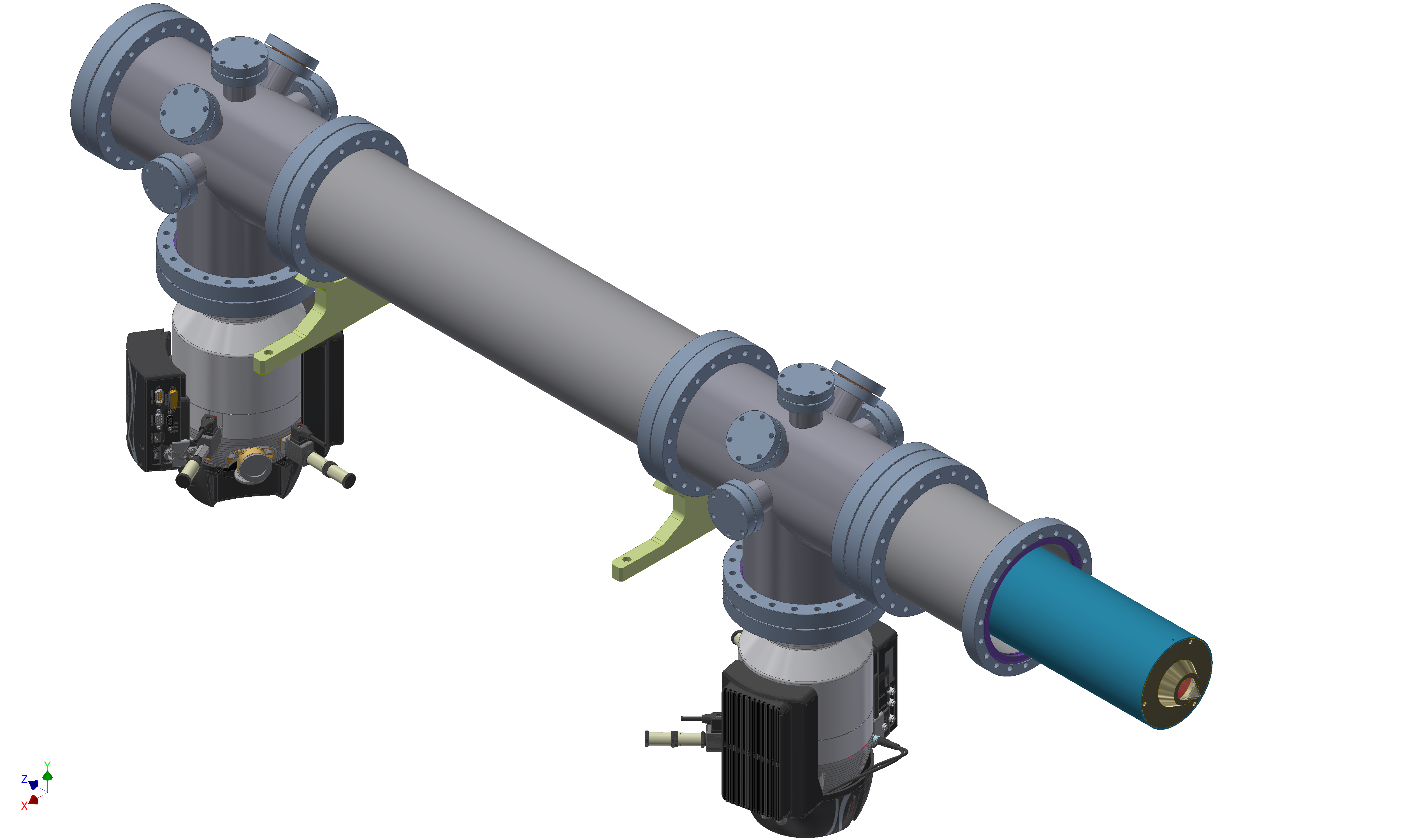
The layout of the magnetic bottle electron spectrometer is under design and the outer parts are currently being manufactured. They are designed such that the complete spectrometer can be detached from the main vacuum chamber by untightening only one flange. This allows easy exchange of the spectrometer with other instruments. The image on the right illustrates the design. When attached to the main chamber, the blue part will be located in the main chamber.
The spectrometer has a number of ports where feedthroughs for the coil current and voltages for decellerating electrons will be equipped.
The detector is the RoentDek model DET75 with a phosphor screen anode and a viewport to examine the phosphor screen with a CCD camera.
Setup
The layout of the setup, i.e. vacuum chamber and supporting frame, is designed to maintain mobility. It will be possible to use the setup at the FLASH1 beamlines BL2 and BL3 and the beamline FL24 of FLASH2. To fit to the beamlines, the frame will be adjustabe in height. Furthermore, fine adjustment to the FEL beam is possible due to horizontal shift of the frame and a rotation around a vertical axis in a limited region.
The sample will be delivered from the top via a capillary oven and the photoelectron spectrometer is perpendicular to the viewing plane.